TRIBOLOGY
SYSTEMS,
INC.
239K
Madison
Avenue
Warminster,
PA
18974
USA
(610)466-7547
LEW4TSI@AOL.COM
www.tribologysystems.com
Executive Summary
Tribology Systems, Inc. (TSI) is marketing ultra-low friction ball and roller bearings and slow discharge flywheel-based energy storage. TSI’s patented flywheel technology is based on the company’s bearing technology, which has lower friction than even magnetic bearings and can operate maintenance free for ten to twenty years in the vacuum required to eliminate windage in flywheels.
It is now generally accepted that energy storage will play an important part in the future electricity distribution infrastructure. It is finding its use throughout the grid helping firming up renewable energy, provide frequency and voltage support to the grid, provide demand reduction at the substation level, and provide increased power reliability and backup at the end users. Today, most slow discharge applications are served by sodium sulfur batteries, whereas fast discharge applications are served by a mix of lithium ion batteries, super capacitors and flywheels. However, it is also generally accepted that most battery technologies are limited to operate in a relative narrow temperature band and they may have a service life less than ten years. Current flywheel technology is also limited to fast charge / discharge operation due to limitations in the magnetic bearing technology they use.
There is currently a void in energy storage solutions that can operate up to the twenty years required by utilities and many equipment manufacturers with no or minimum maintenance service over a wide range of temperatures and operating conditions. TSI has demonstrated that its flywheel technology can overcome the limitations posed by the existing battery and flywheel technologies, and TSI has identified a market segment for a 40kWh flywheel that up to now has been ignored.
The new elevator technology allows for significant energy generation during operation, but due to local regulation and circumstances the energy may be dissipated as heat or it is returned to the local grid uncontrolled. A 40kWh flywheel will be able to interface with most existing elevators and provide local storage for the regenerated energy. The stored energy can then be used by the elevators when needed. Additionally, the flywheel would provide backup power to the elevator in case of a blackout and it can also condition the power used by the controllers, as they are increasingly more susceptible to voltage fluctuations in the power supply.
There are more than 60,000 elevators in New York City alone representing more than 3GWh of potential storage, in addition to large numbers of elevators in other large cities in the world. With an average lifespan of 20 years this translates into a 150MWh potential market annually. For New York, the proposed flywheel would help increase the penetration of new elevators with regenerative braking, with the associated environmental and energy benefits. The same benefits are available for PV farms, other renewable energy sources and utility load leveling.
Tribology Systems Inc was founded in 1989 and is headquartered Warminster PA. TSI’s core expertise is centered on ball and roller bearings. The founder, Lewis Sibley, is an expert in the technology of ball and roller bearings, rolling and sliding contacts and their lubrication. He is an expert on state-of-the-art silicon nitride ceramic and solid lubricants for extreme bearing operating conditions, and his work has led to numerous patents. He has published many peer-reviewed articles and co-wrote the quintessential text book on the science of ball bearings. The focus at TSI has been to develop new bearing products and introduce them into new applications. One notable application is the slow discharge flywheel originally developed for Bellcore. TSI already has a sales pipeline of several millions for ball bearings. The company also sees significant interest from the transportation market for TSI’s 150Wh flywheel originally developed for Bellcore and its 1kWh flywheel originally developed for a South African client. TSI has a Letter of Intent from an overseas company for an elevator back-up product, and Schindler Elevators has also shown interest for the same product.
Problem Statement and Proposed Solution
The Problem
Traditionally electricity supply has been serviced by
relative few large generation plants providing electricity to a
combination of mainly directly powered motors and incandescent lamps.
The system worked with a relative large overcapacity and the loads were
less affected by short irregularities in the supply. Today’s
electricity infrastructure is undergoing a major evolution driven by
the introduction of distributed generation, some of which is in the
form of renewable generation from wind and solar and by nature not
predictable, and the proliferation of electronics on the user side.
The electronics are much more susceptible to variation in grid
voltage and will shut down due to any irregularity.
It is generally accepted that energy storage will play a critical role in stabilizing the grid in general. There are currently three public funded grid related energy storage projects. Two of the projects address frequency support and the last project provides load shifting at a major bus terminal. However, there is one distributed generation source that until recently has been totally ignored: All elevators generate electricity when they brake. The generated electricity has historically been either converted to heat (and thereby put extra load on the building HVAC system) or sent back to the local grid uncontrolled. In older systems the amount of electricity sent back was minimal due to inefficiencies in the drives. However, with new gearless and permanent magnet motors being used, significant amounts of electricity can be sent back to the grid, which can disrupt the power quality locally. Based on conversations with elevator manufacturers and our own observations, a large office building may have 32 passenger elevators with an average motor rating of 51kVA. In a worst case scenario the combined elevators can pull more than 1.5MW in short 5 to 10 second bursts and upon braking send an equivalent amount of power back to the grid. This can potentially be very disruptive for the local grid if it is operating at its peak due to i.e. a hot summer day.
There is currently a petition with the New York State Public Service Commission to equal elevator regeneration with renewable energy such as wind and solar. If that petition is approved, we can expect the conversion to high efficient / high regeneration elevators will speed up.
In addition these new systems use variable frequency motor drives and small computers for their operation, and they are very vulnerable to bad power quality. According to a major elevator manufacturer this has led to frequent interruptions (= stuck elevator) while the system reboots.
Pairing the
elevators with an energy storage device would address both the
uncontrolled regeneration and the power quality issues. There are a
number of reasons it has not been done widely yet:
Until
recently
the amount of regeneration was small and the cost of electricity was
low.
- No current energy storage device could match the twenty years design life of the elevator.
- Large chemical battery banks may be environmentally unacceptable in large buildings.
- Capital and service costs were too high for energy storage
Based on our own market research, elevator motors in high rises can range from 35 to 100 kVA, and an ideal energy storage solution would have the following specifications:
- 40kWh / 80kW minimum peak
- Fast response time to switch between discharge (elevator start) and charge (elevator braking)
- Capable of slow discharge to provide extended back-up power
- 20 years’ service life with minimum maintenance
- Low capital cost
- Modular to fit through a standard door opening and be transported in a standard service elevator.
TSI’s
Current Technology
TSI’s first entry
into the flywheel market was as a supplier for a United Technology
prototype in 1994. The 0.5 kWh flywheel was aimed at the electric
vehicle market and used magnetic bearings for its primary bearing
system and TSI’s solid-lubricated hybrid-ceramic ball bearings as
backup. The team found that the capacity loss was reduced when
the magnetic bearings were disabled and the rotor was carried by the
TSI bearings. The project was terminated when the EV market did
not materialize at that time.
Encouraged by these results TSI continued to pursue a flywheel design with fewer moving parts. The figures below illustrate the difference between the standard magnetic bearings and TSI’s proprietary solid lubricated bearing technology. It is obvious that the TSI solution is considerably simpler with fewer parts.
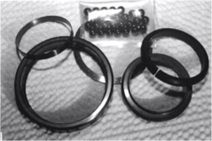
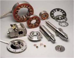
Figure 1: TSI solid lubricant bearing to the left versus SKF magnetic bearing to the right
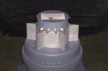
The first TSI flywheel prototype, in the early 1990’s, stored 500 Wh of energy at 30,000 rpm and ran successfully hundreds of times. TSI subsequently got a development contract for a 150Wh flywheel from Bellcore. The application was aimed at distributed back-up of fiber-optic communication lines. The low component count and final product is shown in the figure below.
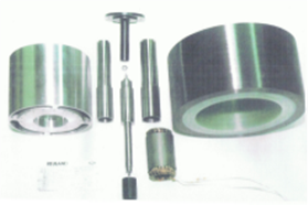
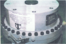
Figure 2: The Bellcore 150Wh flywheel
In addition to the low parts count the design also have some very unique features that allow for a very compact design, and a patented mechanical rotor-dynamics control system that allows the flywheel to be used in a dynamic environment such as vehicles.
After the successful development of the 150Wh, TSI was contracted by a South African customer to develop a 1kWh flywheel. This product is shown below and a number of entities have shown interest in this size for transportation applications.
|
|
|
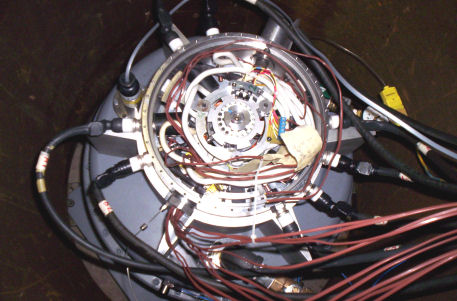
The first generation flywheel used a permanent magnet motor / generator. However, in order to maximize the round trip efficiency, TSI in collaboration with an electronics engineer has introduced a switched reluctance motor / generator (“SRMG”). The technology is not new, but it is only now that motor control technology has caught up to take full advantage of the technology. Unlike permanent magnet motors, which rely on scarce rare-earth elements, the SMRG only relies on a simple laminated metal structure that is only excited when needed. It results in no magnetic flux during free spinning, which would otherwise cause the flywheel to “self discharge” as seen in other commercial flywheels.
Proposed Solution
TSI has already proven that the TSI solid lubricated bearing system can be used for flywheels of 150Wh and 1kWh. TSI has already developed larger bearings for use in light rails and petro-chemical pumps, and similar sizes can be used for the larger 40kWh product.
A schematic representation of the 40 kWh flywheel is given in the figure below and described in more detail in the following.
Figure 4: Schematic representation of the 40kWh flywheel
Mechanics: Inside a vacuum enclosure, both a composite flywheel and a motor/generator are mounted on the same shaft, supported by ceramic ball bearings. Power supplied to the motor accelerates the shaft, storing energy as the kinetic energy of the flywheel. As power is required to a load, the motor converts and functions as a generator, slowing down the shaft, thus regenerating the energy back to the load.
The amount of energy stored is determined by the size, weight and maximum allowable speed of the flywheel within its centrifugal strength limits. The exact amount is a function of the square of the speed of the flywheel. The amount of power is determined by the rated power of the motor/generator.
Tested and proven, TSI’s patented bearings run continuously in a vacuum, maintenance-free for 10 to 20 years. The rotor runs up through its critical speed smoothly, using a patented Flexlift® mechanical vibration isolator, providing no more than a few tenths of a G vibration, running slowly over the entire design speed range.
TSI incorporates extremely-low-friction bearing and completely-mechanical zero-damping rotor-dynamics control features. Together with a new high-efficiency, high-power motor and driver we project very low losses for the flywheel energy storage/regen turn-around. Compared to the other commercial flywheels from companies such as Beacon Power and Active Power, who use magnetic bearings, our design utilizes significantly fewer and cheaper parts.
Composite Rims: Each rotating flywheel or “rim” in the system is made of bi-annular carbon fiber composite material. To reduce manufacturing costs and maintain quality control we are contemplating making composite “rims” in house in the future. For this project we will outsource the manufacturing of the flywheel to a proven supplier.
Switch Reluctance Motor and Controller: The controller is made up of three discrete computer boards and special embedded software, box-mounted, adjacent to the flywheel, and provides:
- Output range: 1kW
up to 100kW load
- SRM model: SRB280L, or equivalent, and SR165L
- Load types: 12V DC , 48V DC and 400V DC 2, 3 or 4-phase drive motors with throttling and regenerative braking
- Input/output types: 240V AC split phase, 360V AC 3-phase, 480V AC 3-phase.
- Dimensions: fits into a 12" x 20" x 8" space
- Load balancing across multiple controllers
- Sensor-less control
- Maximum convection cooling with thermostatically controlled supplemental fan
- Minimum 100,000 hours operation (10 yrs) time to failure
- Digital output feed for "Estimated Power Remaining" digital display
- Ethernet, USB, CAN or MOD-bus to remote control computer
- Built-in diagnostics and event logging
Motor
Specifications:
1. Input and
Output power range: 1kW up to 100Kw output
2. SRM model:
2-phase or 3-phase, multiple stator coils
3. Operating RPM
range: 0 to 25,000
8. Sensor-less
Control
9. Maximum
Radiation Cooling
10. Time to
Failure: Minimum 100,000 Hours of Operation (10 yrs)
Alternative
Solutions and Why the Proposed Solution Is Superior
Current flywheel solutions are too expensive for broad
deployment. Furthermore, they typically employ magnetic bearings,
which limit the applications to short duration discharge.
Existing battery technologies operate only in a narrow
temperature range, and their service life is typically five to ten
years and not the 10 to 20 years required by certain customers such as
electrical utilities and elevator manufacturers.
TSI’s flywheel addresses all these shortcomings, and it is furthermore projected to have an energy density which is very competitive to lithium ion battery packs, which are the current state-of-the-art in batteries.
Barriers
to
Market Entry and Ability to Overcome These Barriers
The primary barrier to market
entry is gaining market acceptance. Lux Research predicts
that the overall market for energy storage will grow from $21.4 billion
in 2010 to $44.4 billion by 2015. Smart-grid storage will make up
the largest energy storage market growing from $5.4 billion in 2010 to
$15.8 billion in 2015. There is not a clear technology winner in
the energy storage market, even though lithium ion batteries have
received significant public and private investment money in the last
couple of years. Furthermore, none of the current technologies
addresses some of the fundamental issues potential customers have with
cost and service life. By initially focusing on niche markets
that are not served by existing products because of their shortcomings,
TSI plans to gain significant traction, which can fuel the initial
growth. The company already has indications from potential
customers that they will buy significant numbers of the units if TSI
can deliver the 50kWh product. TSI has several patents on the
ball bearing and flywheel technology issued in US and selected
countries worldwide.
Design and Manufacturing of Metal Parts. The flywheel contains a number of cast and machined parts. The containment housing and the flywheel hub must be cast and subsequently machined. The flywheel shaft and other parts need to be machined. TSI will finalize the design of the parts, which will include detailed 3-D CAD drawings and stress calculations of both the rotor and the containment housing. Based on the drawings TSI will work with selected suppliers to cast the parts and have them machined to the exact dimensions. After we receive the finished parts from the suppliers, they must be carefully inspected for defects and dimensional errors.
The parts in this task potentially have the longest lead time and we will work with our suppliers to ensure on time delivery.
Design and Manufacturing of Motor / Generator. The VSR motors used in TSI’s current flywheels were purchased from a Japanese manufacturer and will be used in the first prototypes on this project. Rotor and stator stampings will be purchased from a domestic manufacturer to our specified designs and assembled either in-house or at another motor manufacturer.
Design and Development of Flywheel. In order to provide sufficient energy storage and power in a compact, light-weight enough package to meet the requirement of over 100 Wh/kg total entire-system weight, TSI proposes to use an advanced-technology carbon-composite flywheel rim, similar to the one used in TSI’s 1kWh product. This flywheel rotor will have the same basic type of successfully-tested FLEXLIFT® vibration-isolation system as the 150Wh and 1kWh products and the above variable switched-reluctance (VSR) high-power motor/generators. The biannular glass/carbon fiber composite rims will be purchased from an experienced vendor initially, then later a winding facility will be set up in-house to wind rims on a heated mandrel according to a proprietary tension/temperature sequence, then machined into individual rims as required.
Control Module Development. The SRM controller for the current 1kWh flywheel unit requires some upgrade and modification to work for the 40kWh flywheel unit. The controller consists of six modules: 1) the input charger which takes line input and converts it to the internal bus voltage of the motor/controller, 2) output converter which converts the motor/controller bus voltage to the output load voltage, 3) pulse generator module which determines the timing and pulse width of the pulse driving the motor coils, 4) Power driver pre-amplifier which amplifies the pulse and mounts outside the flywheel container, 5) Power driver final-amplifier which is mounted inside the flywheel container, and 6) the switching transistors mounted inside the flywheel container. The design issues with this upgrade and modification are:
- Modify the input charge which now converts 115V AC to the 48V DC motor/controller bus to convert 115V AC to 600V DC for the motor/controller bus for the 40kWh flywheel, and test,
- Modify output converter which now converts the motor/controller bus voltage of 48V DC to 110V AC to convert the 600V DC of the 40kWh flywheel motor/controller bus to 110V AC load voltage, and test,
- Split the current 1kWh power driver module into three modules as described in above paragraph, items 4, 5, 6 for the 40kWh flywheel, design new PC boards, and test,
- Design mounting and power feed-throughs for the switching transistors,
- Modify vacuum container cooling fins to dissipate the additional heat generated by the switching transistors, and test,
- Design remote monitoring for the additional controller modules inside the vacuum container.
After the modifications have been done, we will do the preliminary programming to drive the motor / generator. Especially the generation part must be carefully worked out as the coils must be energized before power can be extracted from the newly generated magnetic field.
Prototype Assembly, Testing and Optimization. The assembling consists of the following steps:
- Assembling the rotor with the TSI bearings and the motor / generator.
- Balance the rotor – at 25,000RPM even a slight imbalance will cause unacceptable vibrations and stress leading to premature failure.
- Bench top synchronization of controller with the rotor – ensure sensor-less operation works at low RPM and the motor / generator performance is optimized at this level.
- Final mechanical assembling inside enclosure.
- Integration of controller components with flywheel and degassing of all components under vacuum.
- Bring the rotor up to maximum speed to ensure mechanical integrity.
- Final optimization of motor / generator performance.
As part of the final assembly, we will also generate a complete engineering drawing package and detailed Bill of Materials.
Individual
Qualifications
Ib Olsen, Acting President – Tribology Systems, Inc. /
Founder and Principal – IBD Associates
(Project Manager): Dr.
Olsen is a serial entrepreneur and an authority in
the field of advanced
battery and fuel cell development. He has authored
numerous papers and scientific publications
and he is an invited speaker at industry conferences.
He has implemented various scale-up and
commercialization concepts for battery-related products
within a Fortune 500 company and
various successful start-ups. Dr. Olsen’s groundbreaking
work in the battery and fuel cell
technology field has awarded him more than 30 patents.
He co-founded IBD Associates, a
successful consulting company to the financial and
CleanTech industry, where he is still active.
He was the founder CTO at Gaia Power Technologies, which
was the first company in US to sell
distributed energy storage on a commercial basis.
He was in charge of product definition and
development and IP, and he secured more than $3 million
in product development grants from
State and Federal entities. The company was sold to
the lead investor. Additional previous
employment includes eVionyx, Saft America and Valence
Technology. Dr. Olsen holds a Ph. D.
in Chemistry from the University of Odense in Denmark and
a M.Sc. in Chemical Engineering
from Denmark’s Technical University.
Lewis B. Sibley, Founder and CTO - Tribology Systems Inc
. Mr.
Sibley is an
expert in the technology of ball and roller bearings,
rolling and sliding contacts and their
lubrication. He is an expert on state-of- the-art
silicon nitride ceramic and solid lubricants for
extreme bearing operating conditions. Prior to
founding TSI, Mr. Sibley worked at Battelle
Memorial Institute and SKF Industries for many years.
He has authored or co-authored more
than 70 papers and seven chapters in technical books and
journals. He holds 14 patents in the
technology. He is a Life Fellow of the American
Society of Mechanical Engineers (ASME), and
a Fellow of the Society of Tribology and Lubrication
Engineers. He holds a BME from
Rensselaer Polytechnic Institute and did graduate studies
in Mechanics and Metallurgy at Ohio
State University and Liberal Arts at Ohio Wesleyan
University.
Richard E. Ferguson, CEO – Tribology Systems, Inc. Mr. Ferguson has extensive automotive background with Ford, Nissan, Mercedes Benz and Delco Remy. He has served as board member for ISDA, a publicly traded company whose core business is buying, processing and marketing scrap metals and recyclable materials for domestic users and export markets, and also offers commercial, industrial and business customers a variety of programs and equipment to efficiently manage waste. He was responsible for the generation of new business opportunities for the existing business, which was steel processing and a service center, looked for new business possibilities through possible acquisitions, alliances and joint ventures, and provided market research and insight, insured appropriate learning into sales and new business development activities, help create and start up fabrication division and represented the company at numerous trade shows and conferences. He worked with the Access Group (TAG) located in Nashville, Tennessee and worked with companies that needed a solution to achieve bottom line positive results using his operational skills in plant start ups, product launches, and continuous improvement initiatives. Mr. Ferguson graduated from Winston Salem State University with a bachelor’s degree in Business Administration and is utilizing his experience in lean enterprise methodology, plant consolidations, material management and quality implementation to achieve needed results.
Paul Albert, CFO - Tribology Systems, Inc. Paul
is a seasoned financial
executive
with more than 30 years of experience on Wall Street and
the stock market. On the floor of the
NYSE and the ASE he has worked for Kaufmann Alsberg, who
were members and floor brokers.
Other firms that he has worked for were Lehman Bros.
Delta Funding Corp., and JMF Funding.
As an expert on equity
trading, debt financing and commercial loans, Paul has also worked with
Handtrade.com as their National Sales Manager, principal
and the head trader for Dillion Securities Corp,
a nationwide broker
dealer where he ran one of the first pilot programs for the creation of
the NASDAQ
trading system. He was a principal of BG Capital, a New York
broker dealer and later helped develop one of
the first direct access
trading systems and ETN’s, now used extensively by all major stock
exchanges
around the world. Paul earned a degree in Psychology at
the University of Maine, and did graduate work at
The New School in New
York City.
Richard D. Dinsmore, Director of Sales and Marketing –
Tribology Systems, Inc .
Mr. Dinsmore has many years’ experience in technical sales
and marketing, but his background also
makes him ideal to manage the company’s suppliers.
He was the Director of Marketing for Newin Company, Inc.,
importers and marketers of precision casting, forgings, precision machining,
hydraulic components, bearings, ball joints and other
metal formed components. He has worked
over the past 12 years in strategic sourcing specific to
mainland China. Richard also has a
background in finance having worked in a variety of
positions at Farmers Mechanics Bank in
Burlington, NJ. Richard holds a B.S. in
Construction Engineering Technology from Farleigh
Dickinson University, Teaneck, NJ.
Richard Johnston, Director of Electrical Engineering -
Tribology Systems, Inc.
Mr. Johnston is
responsible for all electronic components
and applications, including that of the
motor/generator and controller. He has worked as an
electrical engineer for Bellcore (NYNEX),
Bell Labs (ATT), US Department of State, HRB Singer
Government Systems and Harris
Government Systems. Rich’s skill sets also include
computer hardware and related software
applications, project analyses and planning. He
holds a BSEE from NYU-Polytechnic and a
Master of Engineering Business Administration from George
Washington U MEA (GW).
Mike worked in the machining trades, and received a broad-based training in machining technologies. He was Plant Manager at Insaco, Inc. where he developed novel techniques of machining, grinding and final lapping/polishing of unusual materials, building up the company now recognised as the best and most capable international source of machining ceramics and sapphire. Mike acted as a "hands-on" developer of new and progressive methods to produce ceramics and sapphire to extreme surface finish requirements, producing products with both ultra-accurate dimensional shape control and tolerances, and surfaces having very little or no sub-surface damage for critical industrial applications. His responsibilities at TSI include the development of vendor sources and in-house capabilities for producing ceramic bearing components machined in extremely controlled ways to obtain the finest defect-free finish coupled with novel surface conditioning and controlled metrology methods that result in vastly improved bearing performance and life over current commercial products, thus positioning the company for the rapid production of the next generation of bearing products. Mike has a BS in Business from Penn State, is a Toolmaker and completed a four-year tool-and-diemaker apprenticeship at E.G. Budd Co.